Sinai
Building and Soldering my split keyboard
- 27 Oct 2025
- ⌘
- 5 min read
Table Contents
- 1. Choosing the keyboard
- Must have
- May have
- My keyboard
- 2. Soldering
- 2.1 Preparation
- Tools used
- 2.2 Solder the Diodes
- 2.3 Solder the Hotswaps
- 2.4 Controllers
- 2.5 Sockets
- 2.6 Headers
- Solder the Microcontroller
- Reset and TRRS Jack
- 2.6 Modules
- 2.6.1 OLED
- 2.6.2 Trackpoint
- solder the sensor
- Solder on the controller
- Assembling the sensor
- 3. Assembly
- 3.1 Add-ons
- 4. Software Configuration
- 4.1 Important Notes
- 4.1 Connect to Computer
- 4.2 Install and setup
- Option A: QMK
- Option B: Precompiled
- Option C: VIA/VIAL
- Option D: ZMK
- 4.3 Fix Issues
- Firmware
- Desoldering
- 5. Hands Adaptation
- Ref
[!NOTE] This is the Second part of the split keyboard series. The first part is in the blog moises
1. Choosing the keyboard
Before bought my keyboard I set a list of things my new keyboard should have and may have.
Must have
- Be Hot swappable
- Be QMK compatible
- Have type-c connection
- Have 4 rows (have the number row)
- Have a screen
- track ball/point/pad
- Have tenting support
- PBT Keycaps
May have
- Type C between cable instead of TRS
- Have a rotary switch (for controlling volume)
- Metal Case
- Wireless mode
I have bad and good news after done my research to found my soul mate keyboard. The good news is the one i found that checks all the must, and the bad news is that don’t have any May.
My keyboard
I ended buying a Lily58 choc from Holykeebs, mainly due to they have both OLED, a lot of pointer devices to chose and free shipping. Also they have the Twiligh switches on stock and a good and affordable tenting feet pack.
These are the components I picked for my Split Keyboard:
- Controller: 2x RP2040
- Headers: 2x Custom Low Profile
- Pointing Device: 1x Trackpoint / Right / Opaque Black (acrylic)
- Screen: 1x OLED (with Fluorescent Orange Setacryl cover)
- Keycaps: 58x LDSA Black (PBT)
- Switches: 58x Twilight 35g (linear)
- Hotswaps: 58x Kailh Choc
- Top Plate: 2x FR4 Black
- Case: Printed Purple
- Support: 4x Tenting Feet
- Bonus: 1x Switch / Keycap Puller
2. Soldering
2.1 Preparation
Looks quite difficult and it is to do it correctly, safetly and having the right and good quality tools, be aware that if you choose to solder your own, you may end up having to spend more money than chossing a alreayd soldered one, if you need to buy all the tools. The most difficult part is to solder those tiny Surface Mount Components which are almost if not all the components of a keyboard kit, is recommended to use a soldering paste.
Also is important to follow some video tutorial and learn at least the basic before starting there are good resource on blogs, specialize websites and Github. I watched some youtube videos on how to solder like the ones from Josean or Keebio, also you should learn some safety measures. I also followed various build documentation from some github repos like the corne, Lily58 and holykeebs.
Although of the difficulty at the end most people on the net feel that it was easier than expected, and works after the first attempt only that you will need a lot of hours to finished it, as you need to repeat each step for those 30~50 keys, plus the other unique components installing the TRRS Jack, Reset switches, and Controllers and the screen.
Ventilate the room, turn on the fan, wash your hands, put all the necesary components and tool on the table.
Don’t forget to Read the manual of the tools you are using like the soldering iron.
Tools used
- Soldering iron – I used a $10 dirty cheap borrowed soldering, although many recommend the budget friendly pinecil
- desoldering braid – S-007 MIT 1.5mm x 1.5m
$1 - Soldering tin - Super Solder 0.8mm (without-lead) 100g
$7.4 - Tweezer – Get one with a pointy, sharp tip and an angled one, they are both useful.
- Flush Cutters – Used for cutting pins to length. Sharp and thin at the cutting edge is best.
- Screwdriver – Used for screwing cases and covers to the keyboard.
- Black Marker – A black marker is used to paint the edges of PCBs black for better looks. for best results I recommend an acrylic marker.
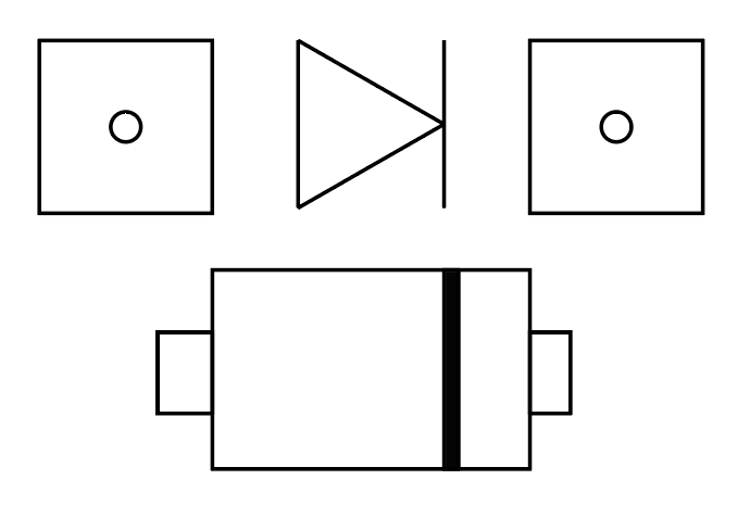
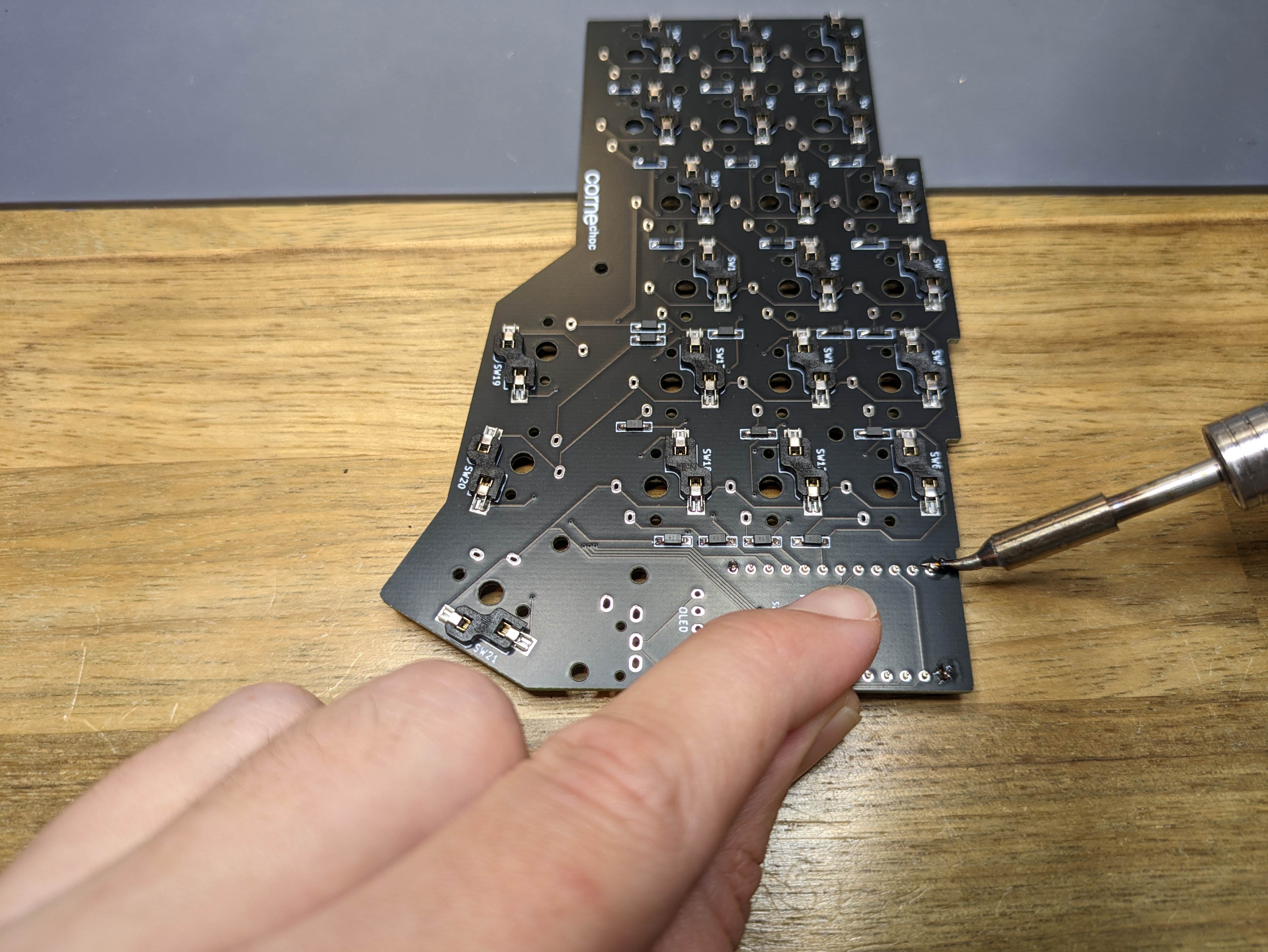
2.2 Solder the Diodes
Remember to clean the soldering iron tip often like every 5 to 10 solders.
Start with the smallest components, the diodes.
- Add Flux on the metal pad
- Add a bit of solder on the diode pads
- Solder one leg
- Check the direction with the line of the diode
- Melt the pad with iron
- Put a leg on the pad with melted
- Check that it is aligned, in the pad and also on the the other pad, so later it will be soldered well on place
- Leave the soldering iron.
- When the tin is sloidify, then you can release the tweezers.-
- Add tin to the other side of the diode
- Repeat for each of the diodes
2.3 Solder the Hotswaps
The switches are far more easy to solder because they are bigger and the have two holes to get in place, so they are less prone to get out of place.
Some guides says to apply solder first on pad then when the first pad is soldered with the Switch solder the other; others says to apply solder to the pads on both sides, because it is difficult to add it later, so please fill it up beforehand.
2.4 Controllers
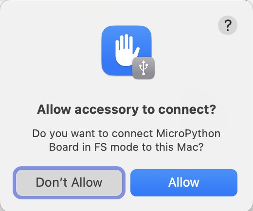
Before doing any soldering on the controller, check the controllers by connecting them to a PC, it should appear a a device like lsub in Linux or MicroPython Board in macOS.
2.5 Sockets
The controller sockets to be properly aligned to the PCB so the controller can be inserted and removed easily, it may be challenging at first.
If both sides have different modules like one have a trackpoint and the other an OLED screen be sure whcich side are your soldering in so you don’t solder in the wrong side.
Put the sockets into the top side of the PCB (the side opposite to where you soldered the diodes and switches). With the sockets still in place, flip the PCB over carefully onto a flat surface.
2.6 Headers
Machine headers have an orientation and should be pushed correctly for best fit. One side is flat, the other has a small bevel to it.
Solder first the first and the last pin and press the board so it will be stay as perfectly together as possible
- put flux on each pin, it will make a big deffrenece on how easy the solder stay well in place.
- Put solder on your soldring iron tip
- Touch the iron tip with solder in the hole with the pine
- Wait around 5 seconds and the hole will suddenly “suck” the solder, filling the hole
- Leave the iron tip and hope the iron have made a perfect cone shape iron the pin and the hole
Solder the Microcontroller
The Microcontroller should upside down
Reset and TRRS Jack
Position and solder them as in the PCB is indicated
2.6 Modules
2.6.1 OLED
- Solder the OLED socket on the part below the controller socket.
- Attach the second base.
2.6.2 Trackpoint
Holykeebs trackpoint docs
Check that the modifier can pass through tape the components so they don’t move while soldering
solder the sensor
Mechanically secure the 4 mounting holes on the sensor to the adapter PCB. If your adapter PCB has pads under the holes, solder them. Otherwise, you may use a thick super glue
Solder on the controller
Each column should have an unsoldered pin near the USB connector!
Only Solder the 4 highlighted pins on the adapter PCB.
Assembling the sensor
- Remove the protective film from the surface mounted nuts and cover.
- Put a washer on each nut and screw the cover on.
3. Assembly
Before adding assembly I should check that I can flash the controller.
- Mount the Switches: mine are north facing (the LED passthrough are on the top), so I will mount them with a T shape, but you may have south-facing switches.
- Mount the keycaps: simply press it on the switches, and it will glide slowly in.
- Screw: you should screw the golden metal piece which looks like a churro from both sides. It should be in the middle of the PCB. Screw the screws from both sides of the churro with the case and top plate.
- Feets: Add the bottom silicone feet and the metal tenting feet.
3.1 Add-ons
After assembling it and seeing those two bars of chocolate bars with Lowprokb Ambients, the most silent choc v1 on the market, I think I can raise the bar even higher on my keyboard’s silentness by adding foam. I found that what is recommended is using EVA or Poron foam. The EVA foam is the most used and seems to be easier to cut, and Poron is more premium (around ten times pricier) and dense. There are already cut foam for split keyboards like the Lily58 for $10-20 on Etsy and some custom keyboard shops (kriscables)


keyboard foam from kriscables
4. Software Configuration
My seller said that based on my keyboard configuration, the USB cable should be connected on the RIGHT.
My keyboard supports QMK and VIA. QMK is the most popular software for custom keyboards.
The source code for holykeebs are in in his Github
4.1 Important Notes
- Avoid connecting / disconnecting the TRRS cable when the keyboard is powered. This can short the GPIO pins of the controllers, which is well explained in Gabe Venberg’ blog.
- When pressing the BOOT or RESET buttons on the board don’t use your bare hands, because it may shock your shock fingers if your are touching the pins on the sides
4.1 Connect to Computer
When I connected it to my MacBook, I noticed that the keyboard was not recognized. MicroPython on RP2040 typically exposes only a serial interface, not USB storage by default. Then I check in System Report → USB and then it appeared there, it also appear in the terminal:
❯ ls /dev/cu.usbmodem*
/dev/cu.usbmodem1101
4.2 Install and setup
Avoid connecting/disconnecting the TRRS cable when the keyboard is powered. This can short the GPIO pins of the controllers.
- Using VIAL in the beginning to really explore and figure out the right layout for a new keyboard is kind of fantastic, but after that’s done with, QMK to fine-tune the experience all the way.
- Vial does have more features than VIA, but there are still a lot of powerful features that you cannot do through their UI, like advanced tapdances, achordion, OLED configuration, etc.
Below are some options to configure and flash the firmware to the keyboard controller.
Option A: QMK
QMK is the original and most powerful firmware for custom mechanical keyboards. Programmable by modifying source code in C. Supports complex keymaps, layers, macros, RGB lighting, mouse keys, and more. Changes require re-compiling and reflashing.
Enter the bootloader in 3 ways:
-
Bootmagic reset: Hold down the key at (0,0) in the matrix (usually the top left key or Escape) and plug in the keyboard.
-
Physical reset button: Briefly press the button on the back of the PCB - some may have pads you must short instead.
-
Keycode in layout: Press the key mapped to
QK_BOOTif it is available. -
Get your keyboard firmware.
- Option A: Go to the QMK Configurator to choose your keyboard layout and configure it. After finishing the configuration, you will download the
.cfile. - Option B: clone the repo from your GitHub, the usual will be:
qmk setup <username>/qmk_firmware- In my case, because my fork is not from the main branch, I clone it using this command:
git clone -b my-store-master https://github.com/[user_name]/qmk_firmware.git ~/qmk_firmware
- In my case, because my fork is not from the main branch, I clone it using this command:
- Option A: Go to the QMK Configurator to choose your keyboard layout and configure it. After finishing the configuration, you will download the
-
Flash the firmware
- You can use QMK Toolbox. On Windows, you will download it and install the drivers. On macOS, you don’t need drivers; you only need to install the app from Homebrew:
brew install --cask qmk-toolbox - Or you can use the CLI version
brew install qmk/qmk/qmk - Check if everything is fine
qmk doctor - Use qmk console or VIA to test key inputs and watch for errors.
qmk console
- You can use QMK Toolbox. On Windows, you will download it and install the drivers. On macOS, you don’t need drivers; you only need to install the app from Homebrew:
[…]
Option B: Precompiled
- I download it from holykeebs/firmware Precompiled section
- To flash, we need to get into the bootloader:
- On the RP2040 Pro Micro There are two buttons on the components side of the controller:
- If first time flashing QMK: hold the BOOT button and then press the RESET button next to it.
- If already flashed with a QMK firmware: double tap the RESET button on the keyboard itself.
- On the RP2040 Pro Micro There are two buttons on the components side of the controller:
- Then copy the
.uf2file into the USB drive calledRPI-RP2- In the
RPI-RP2there is a file that have myF2 Bootloader v3.0 Model: Raspberry Pi RP2 Board-ID: RPI-RP2
- In the
- There is a file commands.txt has a list of file name to the make command that produced it and can be used as a reference.
Option C: VIA/VIAL
VIA and Vial can compile and flash it in real time, so it is easier for beginners.
VIA is a user-friendly graphical configuration tool built on top of QMK firmware.
Vial is also a fork of QMK that extends VIA’s features with advanced customization. They have the Web version and a beta App version
Option D: ZMK
Fork of QMK, specifically designed for wireless keybords.
4.3 Fix Issues
You may find some issues after flashing the firmware and using it for the first time, like some keys couldn’t be detected. For me, I have delays and keys output to many times when pressing one time.
Firmware
It may be something related to the software. Be sure you are installing the correct firmware, the one that may be in the docs of your seller. Also, be careful to have the correct version.
Desoldering
If it is hardware-side issues, you may need to desolder and solder again. For desoldering, you will usually need a desoldering braid, also solder wick, but for small joints like GPIO pins or most of the joints in the keyboards, an easy way is using a Desoldering Pump. A good one could be the ENGINEER SS-02 ($20) that is made from aluminium and is made in Japan, but if you will not use it that often, you can buy one cheaper for around $10 from brands like ProsKit or other similar brands. iFixit has one for $4 and has a guide on how to use a Desoldering pump. From Prime, the pump, activate it, desolder a joint, and clean the pump.
How to prime the pump (first pic) and activate the pump (second pic)
5. Hands Adaptation
Monkey type
Switching to Colemak?
Ref
There are a website about keyboards like KBD News and Golem with many split keyboards information, key sounds, where to buy and more. There are some blogs about split keyboards and their build process (armno).
- Keebd from budget-friendly kits(~60$), not too many customizations, from Australia
- Keeb Maker
- Mech Boards The biggest keyboard shop in the UK
- Kriscable – from Portugal